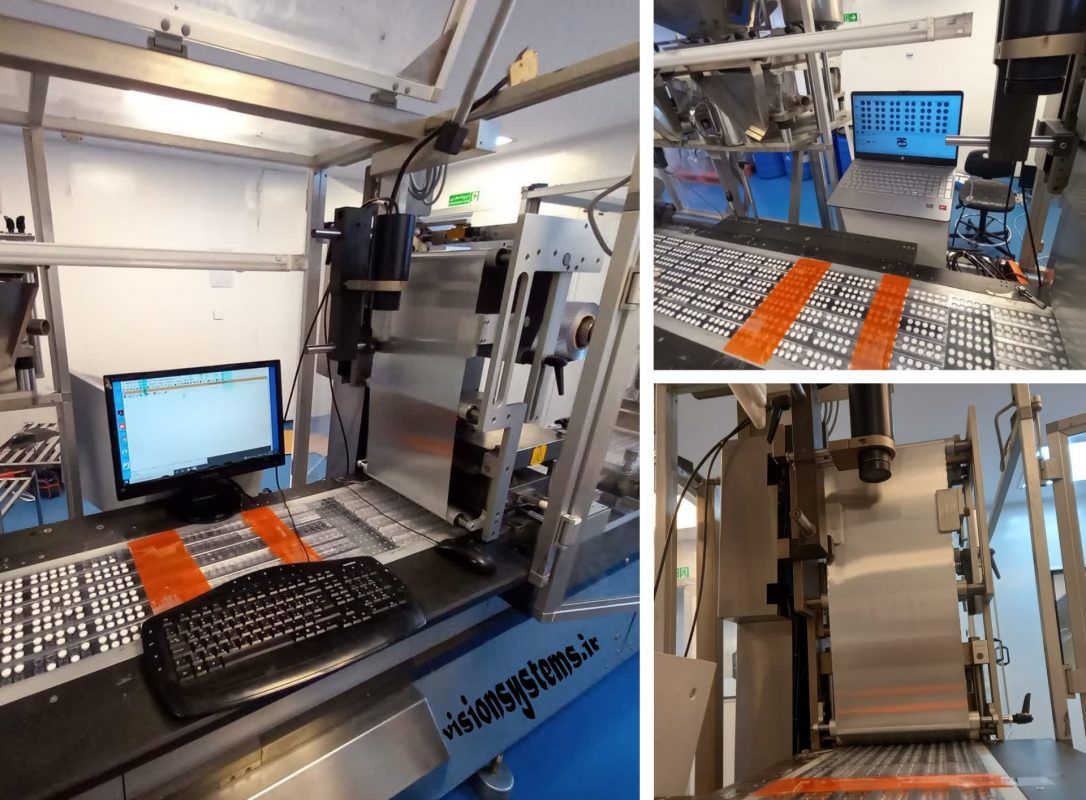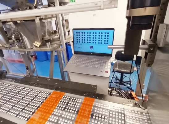
The image above shows the implementation of a machine vision system in a pharmaceutical factory. This project, designed by the Vision Systems team, aims to identify defective, broken, and empty tablets. In this article, we will explain the details of implementing this system. But before that, let’s talk briefly about the blister machine and the role of machine vision in the pharmaceutical industry.
The Most Practical Drug Packaging Machine; Blister Machine
Blister literally means a bubble. In most of these machines:
- A polymer film of PS, PET, or PVC is heated to the point where it becomes formable.
- Under positive air pressure and mechanical tension, it takes the form of a container for tablets.
- The created bubbles guide to the location of filling tablets.
- Finally, the filled containers of tablets are sealed with an aluminum foil under pressure and heat.
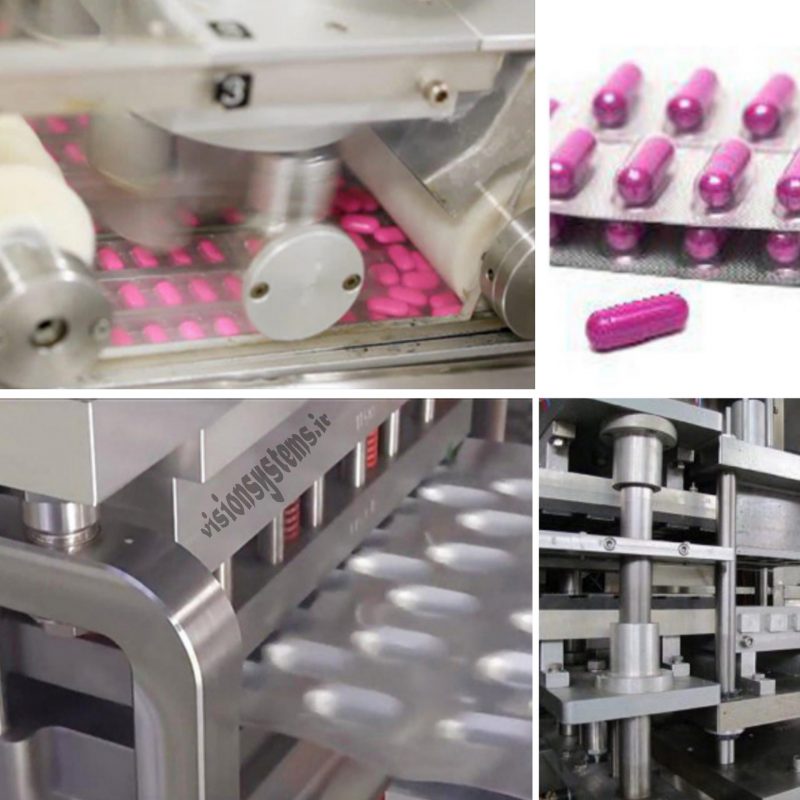
Quality control of tablets in the blister machine is done by machine vision. In the following, we will explain the applications of machine vision systems in the blister machine.
Quality Control of Tablet Packaging with Image Processing in the Pharmaceutical Industry
In various stages of producing a tablet package, vision systems can take over the task of automatic inspection step by step. In the image below, you can see the stages from filling and sealing sheets, print control on the box, control of OCR, etc., to the final stage of sealing and waxing the tablet boxes that these powerful eyes of vision systems handle the inspection task.
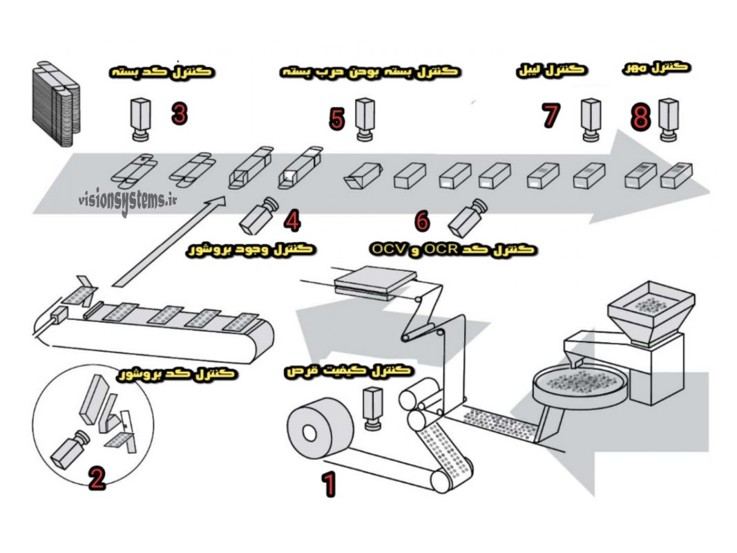
In the quality control of tablet grains in the blister machine, the process of machine vision system is as follows:
1. A camera captures an image with sheets filled with tablets without cutting.
2. The image is transferred to the computer and image processing software.
3. The image processing program identifies the smallest defects in the tablets in a fraction of a second and sends them to the PLC.
4. The PLC activates the defective reject sheet (after the sheet is cut).
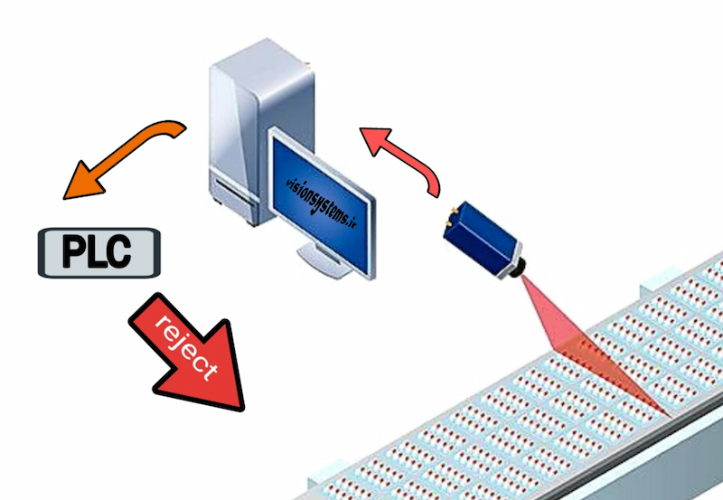
Before installing this system on the blister machine, we have simulated it in the laboratory. Below, we will explain the simulation of this vision system.
Design and Simulation of a Vision System for Defect Detection in the Blister Machine
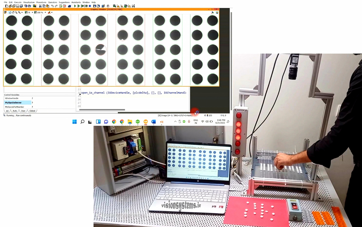
Here, our goal is to simulate the vision system before installing it on the blister machine in a laboratory environment. With this simulation, we can test the blister program and ensure its proper functioning. As you can see in the image, the equipment used in this test includes:
- Basler industrial camera
- Suitable light for illumination
- PLC
- 6 signal lamps
- Transparent sheets filled with tablets
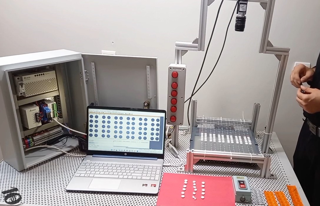
The active brain of this system is the image processing program for tablets in the Halcon software that identifies defects. We will explain more details about the equipment and how the system works below.
Choosing Light and Using Signal Lamps in the Simulation of the Tablet Inspection Project in the Blister Machine
Backlighting is suitable for this project, as it reveals the structure of the tablet in images with dark circles due to this type of lighting. The rest of the image is completely bright due to the transparency of the PVC sheet as a result of the passage of light. In the image below, you see the picture of a large sheet of tablets illuminated from behind in the Halcon software.
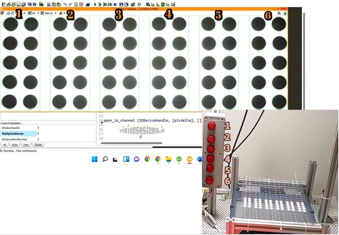
In the image you can see six packs of tablets. That’s why we have used 6 signal lamps, numbered one to six on the image, corresponding to each pack of tablets.
Connections of the camera to the light and washing in the tablet defect identification project
In the laboratory test phase, the camera is connected to the washing on one side, receiving the imaging signal from the washing, and on the other side, it is connected to the light. With each press of the washing, the camera sends the illumination signal to the light and simultaneously captures an image, sending the images to the tablet image processing program. The connection of the camera to the light and washing is illustrated in the image below:
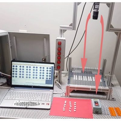
Connection of Blister software to PLC and camera in the tablet image processing program
The Blister software in the hawken is connected on one side through network cable to the camera to process the image as soon as it is taken, and on the other side, it is connected through ethernet cable to PLC to send the reject signal. PLC, upon receiving the error signal from the image processing program, turns on the signal lamp and activates the alarm for a short moment. The connection of the software to PLC and the camera is shown in the image below:
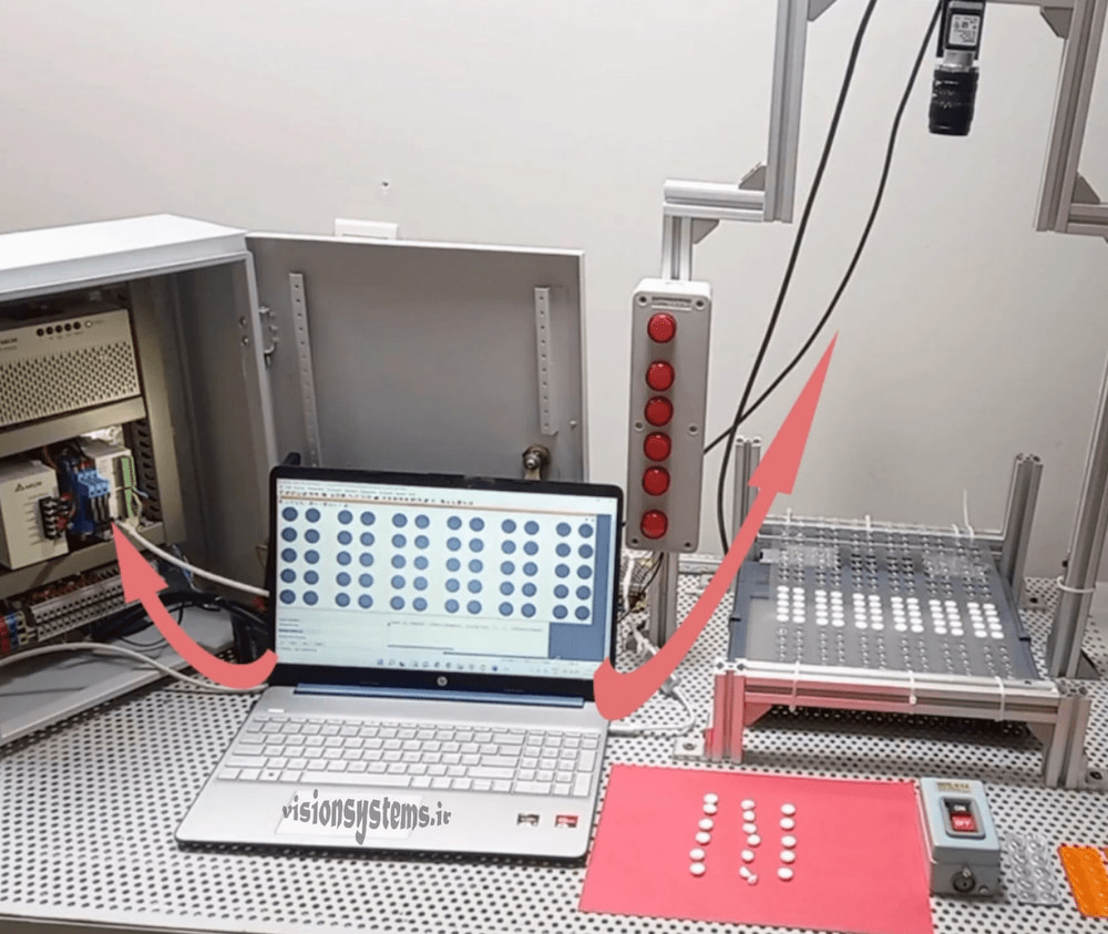
The camera settings for imaging and software connection to PLC are explained in the training course.
Functionality of the tablet breakage and crack identification program in the blister machine
In the program test phase, we send the imaging command through a washing to the camera. The Blister software identifies breakages, filled lips of tablets, or empty bubbles and sends the corresponding signal to PLC. PLC, upon receiving the error signal from the image processing program, turns on the relevant signal lamp and activates the alarm for a very short time. Four examples of the program’s tests are shown below:
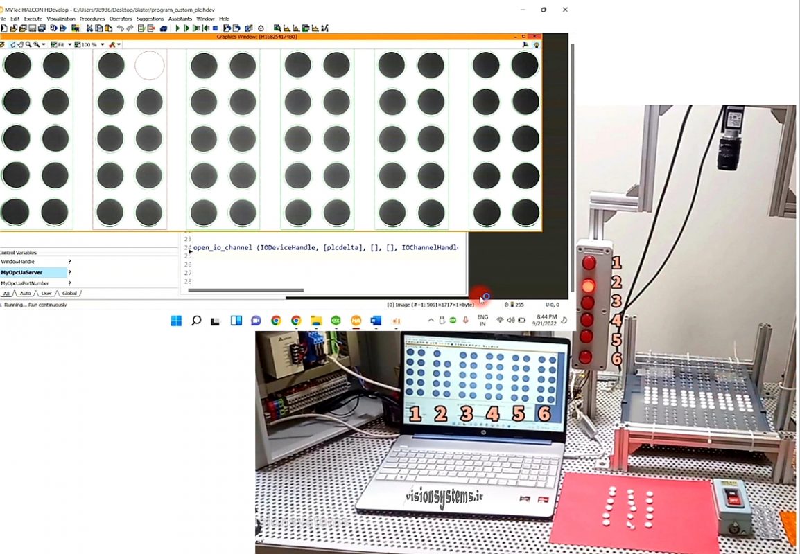
Test 1: Detection of empty bubbles
As an example, in the image below, the program has detected the emptiness of one of the tablets in pack number 2. The empty tablet is marked with a red circle, and the defective pack is marked with a red rectangle. With the identification of the defective pack, the program turns on signal lamp number 2 through PLC.
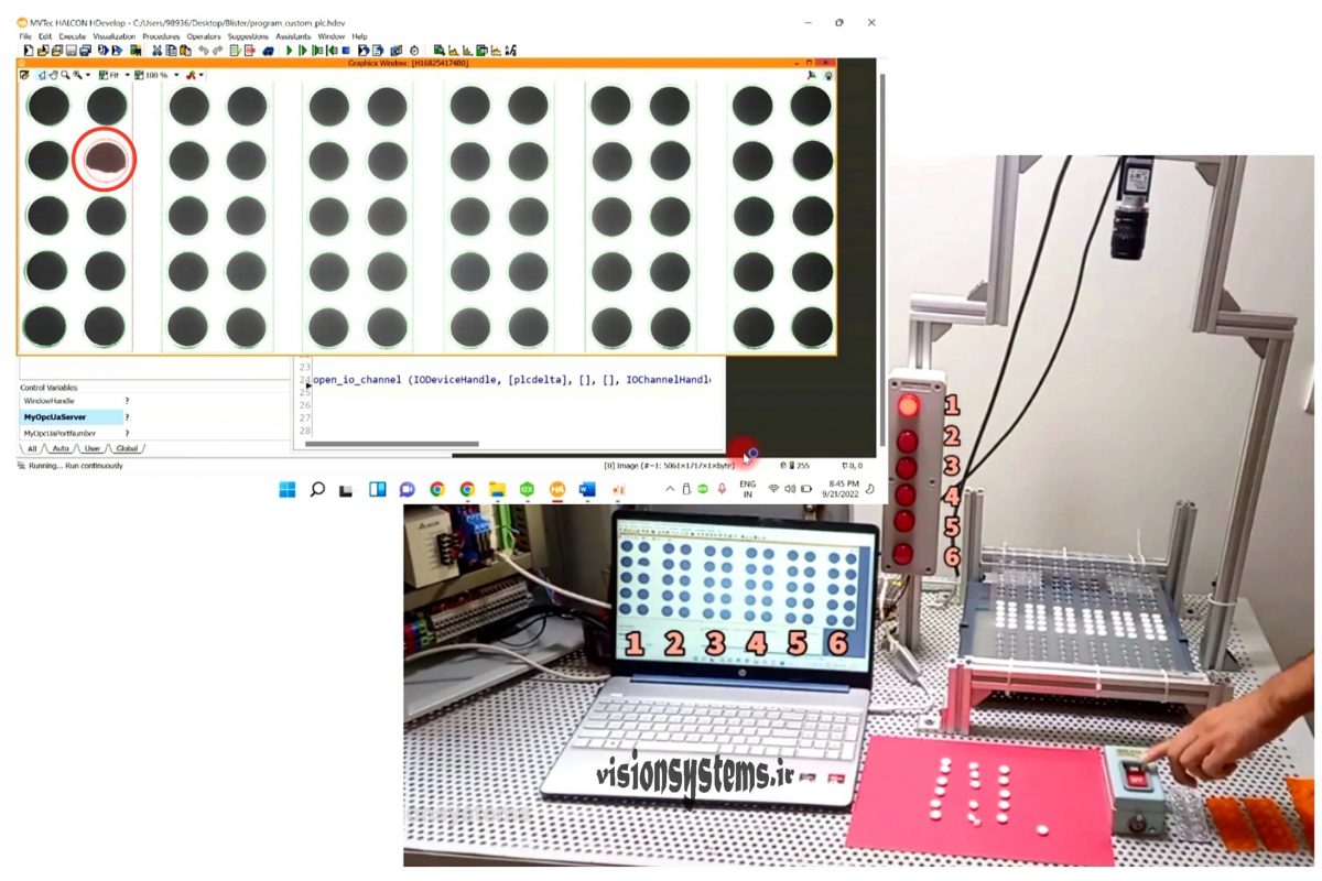
Test 2: Detection of breakage in tablets
The Blister program in Hawken can identify various defects and display the defective tablet and its corresponding pack with a red circle and rectangle on the monitor. In the image below, one of the tablets in pack number 1 is defective, so the relevant signal lamp is turned on.
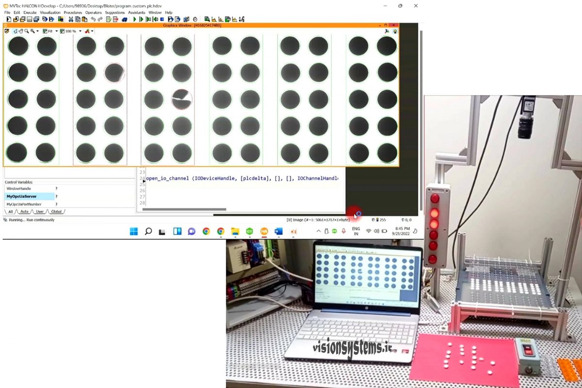
Test 3: Detection of crack and filled lip in tablets
In this test, you can see that two of the tablets in packs number 2 and 3 have cracks and breakages, so signal lamps number 2 and 3 are turned on, and defective tablets and packs are highlighted.
Test 4: Detection of small scratches
As you can see in the image below, the program is able to detect even the smallest defects. In pack number 4, one of the tablets has a very small scratch, which the program has detected. Further capabilities of the program are examined below.
Capabilities of the tablet image processing software in the blister machine
The Blister program developed in this project has capabilities that make it flexible for use in similar cases, including:
- Detection of various breakages and partial cracks or defects in round and oval-shaped tablets.
- Possibility of training the program with new tablet models: For each new tablet pattern, the program learns it once, and in subsequent instances, it recalls that pattern, eliminating the need for retraining.
- Possibility to adjust the program’s sensitivity for detecting various small defects or ignoring them; it is possible to adjust the program to report minor defects or, conversely, to ignore small imperfections.
Practical implementation of the project in the tablet production factory on the blister machine
After the laboratory tests, we implemented this project in one of the tablet production factories. With the tablets passing through the machine, the imaging signal from the encoder of the blister machine is given to the camera. The camera captures images of the tablets and sends them to the Blister program. The program, upon identifying defective tablets, sends the signal to PLC. Then PLC, after the blister machine cuts the defective tablets, rejects them. Twelve tablet packs are inspected per second, which means an average of 720 packs of tablets per minute. In the video below, the project test in the tablet production factory on the blister machine is shown:
In the images below, you can see the installation of the camera on the blister machine and the display of the images of 6 tablet packs on the monitor. All the necessary details for camera and light settings and receiving the reject signal from PLC are fully explained in the training course.
